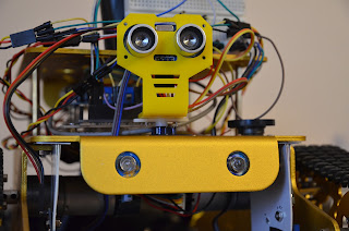
Our robot is not an exception. Adding just couple simple LEDs, changed its appearance radically. Let's see what resources the robotics designers can tap into, and bring more light into their projects.
Standard LED
The first blinking things you notice when starting your robotics journey, are small indicators, soldered right into the Arduino board. These are the simplest and the smallest LEDs you can buy. We did not use them. Such small elements can't produce light, strong enough to be noticeable on a robot. Also, it is not quite easy to solder them using a regular iron.
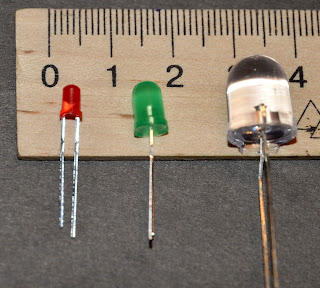
The next best option is a regular cylindrical LED in one of the standard sizes: 3 mm, 5 mm, 10 mm.
You can even buy a special training kit to practice your soldering skills and entertain others with the very simple still quite immersive colorful toy.
|
|
To make sure we never run out of LEDs in our experiments, we purchased from Geekcreit® a big box of them in different sizes and colors. Unfortunately, there are no big 10 mm sizes in this kit.
 |
| Geekcreit® 375pcs 3MM 5MM LED |
You can also find other shapes if needed. For example, square:
 |
| 2*5*7mm Square Green LED |
Connecting LEDs to Arduino
For the very short and very practical overview of the LED technology feel free to dive into the SparkFun introduction to the Light-Emitting Diodes (LEDs).
What you should keep in mind when pairing LEDs with Arduino:
- Current can flow in LED only in one direction, as in any regular Diode. So you should pay attention to the connection polarity. Always connect the positive wire to the longer leg of the LED. If you applied some voltage and the LED does not light up - try flipping it around.
- The resistance of the LED is very small. This means when you connect it directly to the powered Arduino pin, the current can go really high. As a result, your circuit will start playing the game "who gets fried first - LED or Arduino". This can be easily fixed by connecting LED in series with some resistor. It will reduce the circuit current to the acceptable level. Usually, a 220 Ohm resistor is enough (the current, in this case, will go down to 23 mA which is from 5 V divided by 220 Ohm). Most of the LEDs expect the currents not to exceed 20 mA, so you might choose a bit bigger resistor to be safe.
Try to make a habit of always protecting LEDs with the additional resistors. Even simple schemas can appear to be dangerous - keep this in mind when adding more and more load in your Arduino projects.
Having eight LEDs connected the same way to the eight Arduino pins, we created a Christmas garland. Even young school kids can write a program in Scratch or Ardublock to light it up.
Well, maybe the Ardublock program in this picture is not that simple :-)
In the main Arduino cycle (top-left corner) we select randomly one of the blinking modes and store its number in the variable r. Then, according to the mode chosen, we call corresponding blink functions (mode1, mode2, mode3). These calls are repeated 5 or 10 times - whatever looks nicer. Then - everything starts over again.
The file with the program can be downloaded - here.
As you can see in this example - connecting LEDs directly to the Arduino pins is quite resource-consuming. You will quickly run out of free Arduino pins as well as the power reserves of the Arduino board.
The simplest way to overcome these limits is to use shift registers and the SPI protocol. Thus you can drive a potentially limitless number of LEDs using just three Arduino pins. More on this here:
- Jeremy Blum's Tutorial: SPI
- Serial to Parallel Shifting-Out with a 74HC595
- Eight LEDs and a Shift Register
Headlights for the robots
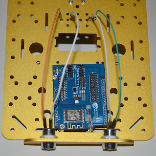
As a part of our robot chassis kit, we received two nice headlights with the big 10 mm LEDs. They can be installed in the special mounting holes. For some reason the LEDs were red-colored, so they went to the rear lights position.
For the front lights, we bought a ready-to-go headlight kit with the LED, lamp cups and wires assembled.
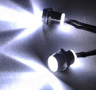 |
| Model Drift Car LED Head and Rear Lights With Lamp Cups |
On arrival, we discovered that actually, we've got smaller 5 mm LEDs. They can't be easily installed on our robot. For sure, a much better choice would be to ask the seller about the cups size BEFORE the purchase. Or buy separately some big LEDs and the 10 mm lights cups. 😕
Fortunately - there is nothing which can't be fixed by a bank card.😁
We made two small pads and installed the headlights on them, and then glued these pads to the chassis.
Having the abundance of the Arduino MEGA pins, we lightheartedly agreed to spend two pins to control front and rear lights directly. The main point to remember here is to connect an additional resistor to each Arduino pin which powers the LED. This will protect the circle from the excessive currents.
RGB LED
A huge leap forward in the LED design was an invention of the RBG LED. In the simplest case, it is a module which has three LED elements inside - Red, Green, and Blue.
 |
| RGB 3 Color LED Module |
Applying different voltage on the pins R, G, and B you can change the strength of each color component. Thus a specific color is formed - the same way as it works for the TFT screen pixels.
The main inconvenience of such LED is that you have to consume 3 pins of Arduino, also these pins must support PWM if you need to cover the whole color space.
In modern devices, such RGB LEDs are used to show the device state. The voltage is applied to one of the pins only (for example Green - working state; Red - battery is flat; Blue - the battery is charging).
For the true enthusiasts, a single RGB LED is close to nothing. Specially for them, the Great Maker invented the RGB LED strip - a potentially endless line of the LEDs connected together.
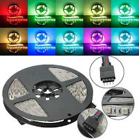
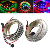
Please be aware - there are two types of the RGB LED strips:
|
|
|
| RGB single color | RGB multiple colors individually addressable |
| Connection: 4 pins - R, G, B, GND (-) | Connection: 3 pins - Power (+), GND (-), Digital Control Line (D) |
| All LEDs in the strip emit the same color, which is defined by the voltages applied to the lines R, G and B. | Each LED can have own color. A special digital protocol is used to specify the color for each LED in the strip. This protocol is handled by a dedicated chip like WS2812 which is built into every element of the strip. |
Operating the individually addressable RGB strips
An individually addressable RGB strip is a universal solution suitable even for the complicated tasks. So we decided to go with it. You can find a more detailed explanation of the working principles here: WS2812 Breakout Hookup Guide. Use "WS2812" as a keyword when searching for more materials - this is the name of the chip which is used the most.
Searching for the RGB strips, we found a nice option for our robot. These are the LED elements which are mounted on a small PCB. They can be connected to each other following any topology you like. Technically this means you can place the LED elements just where you need them and connect as a single "strip", or as a bunch of the independent "strips". You should not worry about the "LEDs per inch" or any other strip physical parameters.
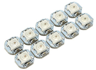 |
| Geekcreit® DC 5V 3MM x 10MM WS2812B SMD LED Board |
A slight inconvenience with such form-factor is the need to solder manually each and every element in the strip. This can be annoying and time-consuming if you are not quite confident in your soldering skills.
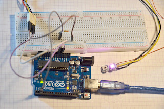
To test how it works, we connected one LED to the Arduino.
Thanks to the Adafruit NeoPixel library, operating the LED strip from the Arduino code pose no complications. You can download and activate this library right in the Arduino IDE. Search for "Adafruit NeoPixel" in the Sketch->Include Library->Manage Libraries… dialog.
All the protocol nuances are hidden behind the curtains - all you need is to specify the LED # and the color to be applied to it.
Ardublock (at least the version we use) natively support this library. My son immediately created a program which once per second randomly change the color of the first LED in the strip.
The program expects that a strip controlling line is connected to the Arduino pin #2. The source code of the program can be downloaded here.
Robot RGB illumination
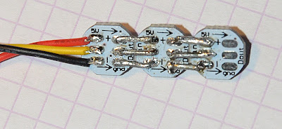
We discovered that two strips with three elements in each provide quite a nice illumination of the bottom of our robot.
Each element is connected to the neighbor by stiff wires. 5 V and GND contacts can be connected to a single long wire - they just supply the elements with the power. Contacts in the middle must be connected in the pairs only - this is how elements can pass the baton just to the next neighbor, not the whole strip.
To make the strip stronger and protect the wires from the unwanted accidental contacts with the chassis, we glued the elements to the piece of the plastic card.
Power was taken directly from Arduino (+5 V and GND). Controlling lines were connected to the Arduino MEGA pins #42 and #43 for the right and left sides correspondingly.
Changes in the robot's firmware
Implementation of the proper lights control required changes both to the remote control application (RoboRemoteFPV) and in the robot's firmware.
Changes in the RoboRemoteFPV were rather cosmetic - no need to analyze them here.
At the robot's side updates are more interesting.
In the AI, we added a new block, which recognizes the lights control remote commands and redirects corresponding calls to the lights management module, which does the real job:
case 'L':
    //  Lights control commands
    // Command length must be precisely 3 characters
    if(strlen(remoteCommand)==3) {
        // the last character specifies if to turn the light ON or OFF
        bool turnOn = (remoteCommand[2] == '1');

        switch (remoteCommand[1]) {
        case 'F':
            // manage the front lights
            robotLights->turnFrontLED(turnOn);
            // send back to the RC application
            // a confirmation of execution
            robotConnector->sendMessage(remoteCommand);
            break;
        case 'R':
            // manage the rear lights
            robotLights->turnRearLED(turnOn);
            robotConnector->sendMessage(remoteCommand);
            break;
        case 'S':
            // manage the side lights
            robotLights->turnSideLED(turnOn);
            robotConnector->sendMessage(remoteCommand);
            break;
        }
    }
    break;
In the lights management module, a few new pieces were added.
Initialization:
// switching the front and rear lights pins
// to the output mode
pinMode(frontPin, OUTPUT);
pinMode(rearPin, OUTPUT);
// Initialize the NeoPixel objects
// to control the left and the right RGB strips separately
leftPix = new Adafruit_NeoPixel(3, in_leftPin, NEO_RGB + NEO_KHZ800);
rightPix = new Adafruit_NeoPixel(3, in_rightPin, NEO_RGB + NEO_KHZ800);
leftPix->begin();
rightPix->begin();
The front and rear lights controlling code is simple. We just set a high or low voltage on the corresponding pins to turn the lights on or off.
void RobotLights::turnFrontLED(bool turnOn) {
    digitalWrite(frontPin, turnOn);
}
void RobotLights::turnRearLED(bool turnOn) {
    digitalWrite(rearPin, turnOn);
}
Toggling the side RGB lights looks even simpler. The ON/OFF flag is stored in the internal variable. Once per second a special background task is checking this variable and changes the state of the strips.
void RobotLights::turnSideLED(bool turnOn) {
    sideLedsActive = turnOn;
}
The most intriguing magic concentrates in the method processTask(). You can easily recognize here the code, from the random-colors blinker, created in the Ardublock before. The only difference - now we have two strips with the three LEDs in each.
Colors get changed periodically, thanks to the multitasking mechanism we've implemented earlier.
void RobotLights::processTask() {
    // is it time to refresh the LED's?
    if(reachedDeadline()) {
        // if the side lights were activated - light the LED's in random colors
        if(sideLedsActive) {
            leftPix->setPixelColor(0, random(0,255),random(0,255),random(0,255));
            leftPix->setPixelColor(1, random(0,255),random(0,255),random(0,255));
            leftPix->setPixelColor(2, random(0,255),random(0,255),random(0,255));
            leftPix->show();
            rightPix->setPixelColor(0, random(0,255),random(0,255),random(0,255));
            rightPix->setPixelColor(1, random(0,255),random(0,255),random(0,255));
            rightPix->setPixelColor(2, random(0,255),random(0,255),random(0,255));
            rightPix->show();
        } else {
            // if the side lights were DEactivated - turn them off
            leftPix->clear();
            leftPix->show();
            rightPix->clear();
            rightPix->show();
        }
        // repeat this again in a while (in 1 second)
        scheduleTimedTask(LED_DELAY);
    }
}
Finally, it happened! Thanks to the new illumination - our robot started to look cool (or at least less weird).
The front LEDs provide enough light to navigate the robot in the complete darkness even using the FPV video stream.
Also, the robot became more visible on the road. This significantly reduces the risk of being trampled by the bigfoots that often roam nearby our robotics lab.







No comments:
Post a Comment