Hardware
The core of the module is based on the ESP8266 microcontroller which itself is very complex and powerful. It can be programmed separately the same way as Arduino, it can work with the same external sensors and modules, and, to be honest, it outperforms Arduino almost in every single nomination.
You can find the most comprehensive and consistent guide on the ESP8266 in the Kolban's Book on the ESP8266.
The breadth of the ESP8266 features is astonishing. We are going to use just a fraction of them and configure ESP13 as a WiFi bridge between the robot's Arduino board and the world outside.
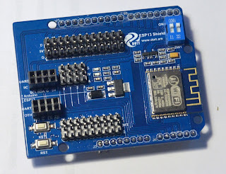
Physically - the module is designed as a shield. It can be installed on top of Arduino UNO (and Mega), connecting directly to the Arduino's sockets.
 In addition to the power lines (5 V and GND), it uses just two other Arduino pins - #0 (RX) and #1 (TX). All other pins are free to be used for everything you like. These free pins are connected to the socket on top of the shield, so you can easily access them even when the shield is installed over Arduino.
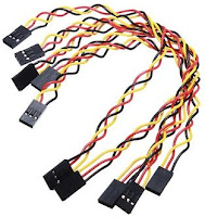
Every Arduino pin is supplemented with the 5 V and GND pins, combined in a single 3-contacts socket. This is the most convenient way to connect sensors and other modules using 3-Pin Jumper Wire Cables. That is a very clever design often missed by most of the board manufacturers.
All ESP8266 outputs are also connected to the socket on top of the shield. There is even a borderline painted right on the board, delimiting the Arduino pins zone and ESP8266 zone.
If you feel confident - you can upload programs to the ESP8266 directly and utilize these pins as well. Just pay attention that Arduino UNO/MEGA use 5 V as a high-level signal voltage. ESP8266 use 3.3 V. Connecting pins with different working voltage can destroy your board.
The only bottleneck in this magnificent scheme is a conflict for the pins #0 and #1. These pins are used by Arduino UNO to perform serial data exchange with the external modules. The issue is that these two pins are also used to upload firmware from the PC. Even if you connected your board to the USB port. When you upload some firmware to Arduino, ESP13 also receives these programming commands and, trying to respond, mangles all the communications. As a result - the firmware will not reach the destination.
Designers solved this issue dully but reliably. In the upper-right corner of the board, you can see two switches which physically disconnect ESP13 from the Arduino serial pins. Turn them ON in regular operations, turn them OFF when you'd like to upload a new firmware to your Arduino board.
For some reason - it did not work for us. Even turning the switches OFF, we could upload nothing. So we had to physically uninstall the shield each time a new firmware was on the way. Fortunately, Arduino MEGA 2560 has 4 independent serial ports instead of one at Arduino UNO. Once we switched to this platform - we just connected ESP13 to the serial port #3 and eliminated the issue forever.
ESP13 is an ideal board for the beginners. Manufacturer ships it with the built-in firmware which implements the following core features:
- WiFi connection set-up is extremely easy. Even easier than configuring a home Internet router. ESP13 has a built-in web server which provides a network configuration page. Just open it in the web browser and configure whatever you need using a human-comprehensible interface.
- Arduino should not worry about all the struggles of the WiFi and IP network connections. Nothing like IP addresses, DHCP, DNS and other boring stuff. Arduino even won't need any third-party libraries. Data exchange is done using a standard Arduino's Serial library. Just read and write to the serial port and the data will be automagically transferred over the Internet.
You can find more details on this implementation in the official board documentation. Fluent Chinese is not mandatory but is highly recommended. 😏
ESP13 Networking Configuration
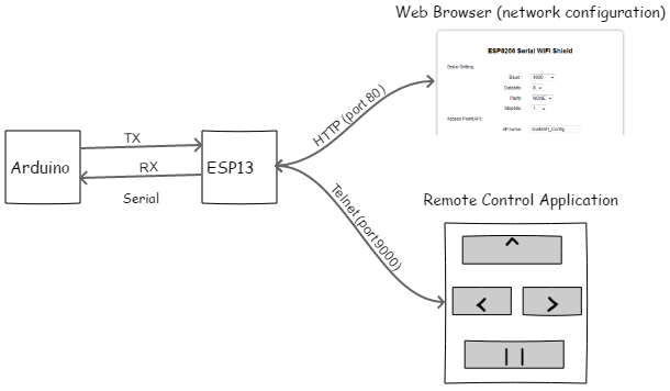
Communications flow for our robot looks like this:
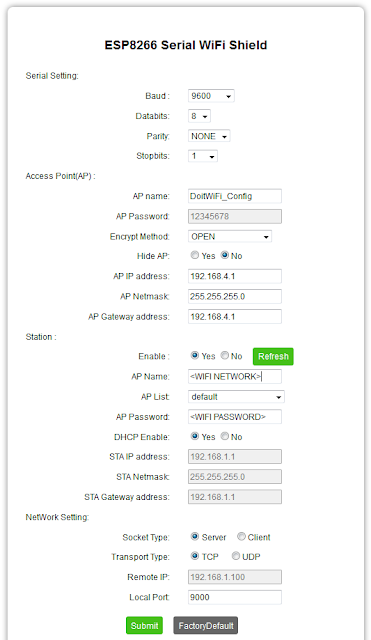
When the ESP13 turns on for the first time it automatically starts Wi-Fi network with the name"DoitWiFi_Config". The password is "12345678". If you connect your laptop or cell phone to this network - you can access the configuration page opening the following URL: http://192.168.4.1.
Here is the configuration of our robot:
Since our robot is going to live in our house, which is already covered by the home Wi-Fi, we configured ESP13 to connect to the home Wi-Fi (AP Name), get the dynamic IP address(DHCP Enable) and wait (Socket Type: Server) for the remote connections over the TCP protocol (Transport Type) at network port 9000 (Local Port).
Having our robot integrated to the home network allows us to connect to it directly from any computer or mobile device. Moreover, using IP Forwarding or SSH tunnels you can control your robot from any location in the world. But this is rather off-topic. Feel free to check here if you need more details on these tricks.
The actual address, assigned to the robot by your home router can be found at the configuration page of your router. If you prefer static addresses - it will also work well. Just fill corresponding fields on the configuration page (STA IP address, Netmask, Gateway address).
You can leave standard serial port configuration (Serial Setting). Make sure in the Arduino code you have the same parameters when initiating serial data exchange.
Remote control application
The elegance of this solution removes all restrictions on the remote control user application. Technically speaking - you don't need any specialized application at all. Anything which can connect to some IP and TCP port can act as a remote control.
Actually - that's how we started. We used PuTTY terminal application as a Telnet client, connecting to the address assigned to the robot by the router (in our case that was 192.168.1.41 port 9000). All characters which we typed in the terminal, were sent to the robot's Arduino serial port, and all responses from the robot were shown back on the screen. Of course, the first thing we taught our robot to do, was how to react to the WASD keys. You will see this code later.
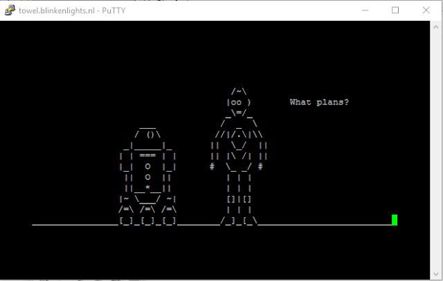 |
| Telnet to towel.blinkenlights.nl to see te whole movie |
No doubt - controlling your robot in the text console is the coolest thing you can imagine in the robotics. But, unfortunately, not everyone shares the same admiration of the black screens and gentle green characters glow. Lots of people enjoy dealing with buttons, icons and other graphical redundancy. So we had to search for something more colorful and user-friendly.
Surprisingly - we could not find any good free (as in freedom) remote control application.
Our robot chassis was supplied with some native remote control applications. According to the descriptions - they should be doing exactly what we need. But an awful habit of switching to the Chinese language at any occasion did not allow them to reveal the full potential.
A big number of the third-party proprietary products pose one significant limitation which made their use also impossible. For some reason, most of them are willing to take a complete control over Arduino, requesting you to upload a specific firmware (firmata) similarly to what Scratch does. This leaves no space for your own code and makes your robot completely dependent on the commands from the Big Brother (remote control application).
More friendly applications propose including into your project their own, usually heavyweight, library, hiding all the details of the message processing from you. Maybe this is good for the usual IoT home automation projects, but our Arduino is too busy managing the robot. We can't allow any secondary function like the remote control wasting precious resources.
Very close to the ideal case is RemoteXY: Arduino control. Its integration with Arduino is a bit complicated since it requires to generate a custom library which needs to be injected into your source code. Fortunately, this library is not too heavy.
The only application which ideally fit our expectations is RoboRemo. It is lightweight, requires no changes in the Arduino program and is very simple to use.
Just in couple minutes we created a simple remote control panel and connected it to the robot.
The "menu" button is always there and gives the access to all RoboRemo functions.
We added buttons FWD, LEFT, RIGHT. They only thing you specify for them (besides the button title) is "set press action". This is a string which is going to be sent to the robot. We set "W", "A" and "D" correspondingly.
For the convenience, you can also open screen "repeat" and set there delay = 500 ms, period = 500 ms for each button. This will ensure your robot will not be flooded with the repetitive commands.
Now it is time to connect to the robot's ESP13 shield. Follow this path: menu->connect->Internet (TCP)->other. In the request window type the address of your robot (in our case it was "192.168.1.41:9000").
If you did everything properly - RoboRemo will connect to the robot and your Arduino will be receiving 'W', 'A', 'D' characters from the serial interface according to the button pressed. Every character is followed by the command termination character (by default it is '\n' Line Feed character - you can ignore it as for now).
You can do a lot of other cool things with RoboRemo:
- Buy a PRO version, so you can place more than 5 controls on your RC dashboard
- Use LED-type indicator which will light up when specific message is received from the robot, for example when robot notifies you that it is ready to accept your commands
- Use component "accelerometr" and control the robot by turning your cell phone in different directions
- Use component "text log" to show on the screen all messages received from the robot - this is a perfect way to see debug information instantly. You wouldn't need to plug your robot to a computer every time something works not as expected
- Replace text labels on the buttons with nice icons (PRO version is required)
To be short - if you feel RoboRemo is what you need - buy PRO version and enjoy. This is a good piece of software.
If you happen to know better options - please feel free to share them in the comments. As for now - we are busy creating our own remote control application. We'll post a review of it once ready.
Handling commands at the Arduino side
Handling commands at the Arduino side is as simple as reading characters from the serial interface using standard Arduino Serial library and reacting to these commands accordingly.
The basic prototype can look like the following:
#include "Arduino.h"

void setup() {

    // set-up the serial interface
    // make sure the speed here is the same
    // as set up at ESP13 config page
    Serial.begin(9600);

    while (!Serial) {
        ; // you need this piece only if you are connected to USB
    }
}

void loop() {
    // did we receive anything?
    if (Serial.available() > 0) {

        // read a character from the serial interface
        int remoteCommand = Serial.read();

        // act accordingly to the received command
        switch(remoteCommand) {

            case 'W':
                // this message will be sent to a serial console
                // it can also toggle some LED on the
                // RoboRemo dashboard
                Serial.write("MOVING FORWARD\n");

                // Full ahead!
                // 255 here means max. power (PWM)
                // 600 is a duration of the action in ms
                // it is important to have a duration here,
                // which is larger than the repeat cycle in the RoboRemo
                // otherwise the robot will hiccup twice per second
                robotMotors->driveForward(255, 600);
                break;

            case 'A':
                Serial.write("TURNING LEFT\n");
                robotMotors->turnLeft(255, 600);
                break;
            case 'D':
                Serial.write("TURNING RIGHT\n");
                robotMotors->turnRight(255, 600);
                break;
        }
    }
}
You can see the whole remote commands processing code in the AI module of the robot's firmware.
Don't forget to download the RoboRemo interface definition. Place it in the "roboremo" folder on your mobile device and import it following these steps: menu->interface->import.
Be careful and always keep your robots under control. Remote Control.


No comments:
Post a Comment